
Creating Box (Finger) Joints In Fusion 360 Using Combine
TL;DR
- Create your components.
- Use Joints to attach/fix the components, and have the components overlap/interfere where the box joints will be.
- Cut away material from Component-1 to form the box joints.
- Use Combine (cut) to cut material away from Component-2
- Use Offset Faces on Component-2 to provide some clearance.
Description
Lately I’ve been creating lots of things with box joints. I design them in Fusion 360 then use a laser cutter to cut them out of plywood. Overtime, my Fusion 360 skills have improved and I have changed how I make my box joints. Below is my current process.
I’ll create two simple rectangular pieces and join them together at a 90d angle.
Using Imperial measurements despite being Canadian. Sorry.
Box or Finger Joint
I’ve been calling these finger joints for the last while, but perhaps they are more correctly called box joints (https://woodshopbits.com/blogs/resources/whats-the-difference-between-a-finger-joint-and-a-box-joint). Though the same techniques would be used in Fusion regardless.
The Process
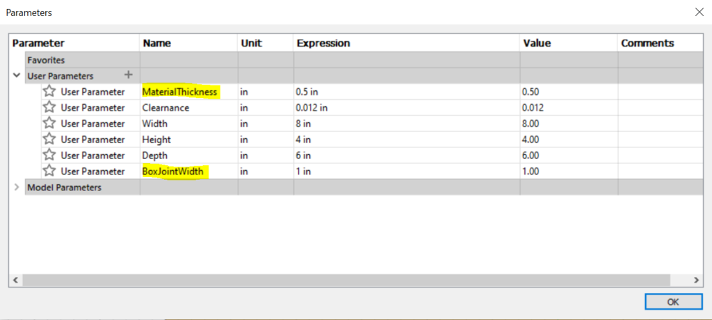
Set up some Parameters. Of special importance, for this blog post, are the MaterialThickness and BoxJointWidth. But of course, use the values that are appropriate for what you are building.
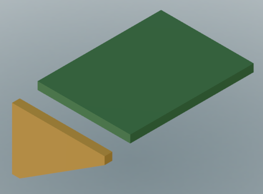
Create two simple components.
Joint your components to fix them in place.
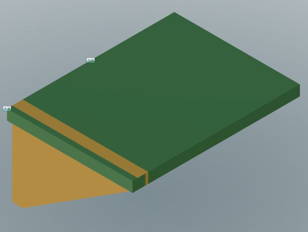
Cut the box joints.
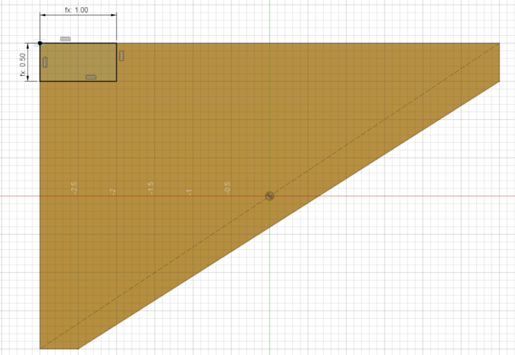
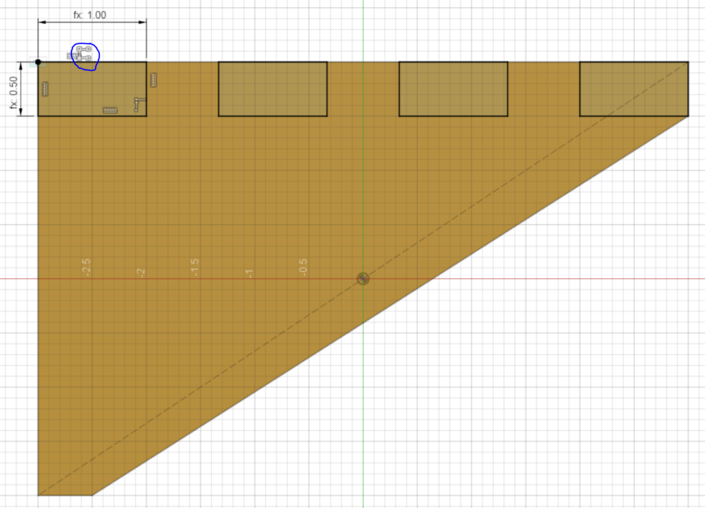
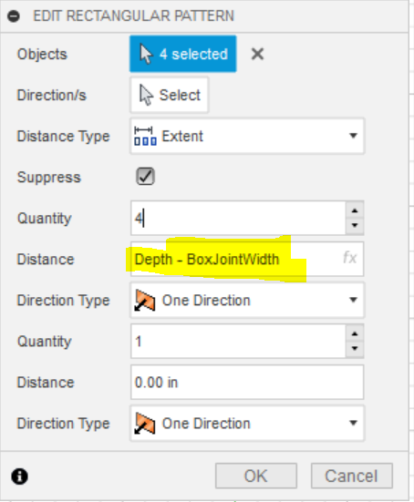
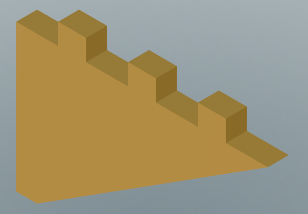
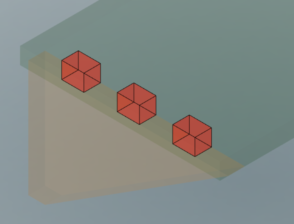
Create a sketch. Draw the first box joint. Then use Rectangular pattern to repeat the box joint across the component. Extrude (cut) the sketch through the component.
Remember, you are sketching the material that you want to be cut away from the Side. So think about whether you want the boxes at the edge of the component or possibly offset from the edge a bit.
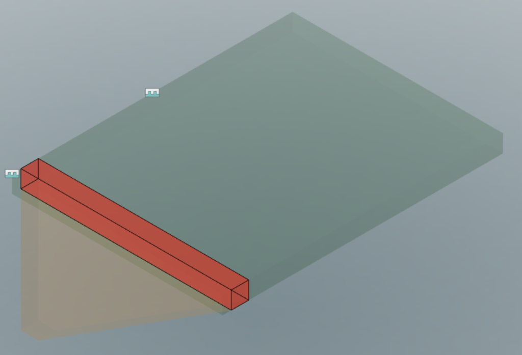
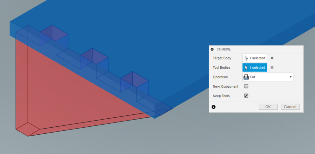
Combine (cut) for a “perfect” fit.
Do a Combine (cut) to remove the interference. Target Body=Top, Tool Body=Side. And remember to “Keep Tools” otherwise the Side component will disappear.
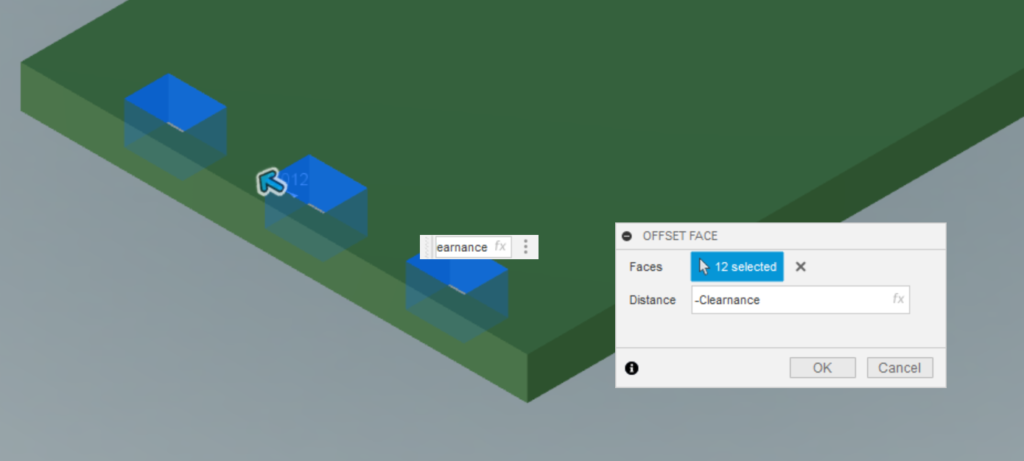
Adding clearance to our box joints with Offset Faces.
A “perfect” fit isn’t so perfect. Once you have made these components as real physical objects, the “perfect” fit is going to require a lot of force for them to fit together. So a clearance will be helpful so we can get the fit we want.
The clearance value you choose will require some experimentation. It will vary depending on your type of material, thickness of material, accuracy of your manufacturing process, and how easy you want these component to fit together.
Use Offset Faces to make the holes from our box joints a bit bigger. Select all the faces of the holes and apply the Offset Faces to them.
If you had large components and many box joints, this may result in a lot of faces to select for the Offset Faces. Here is a script to make this easier (Select Affected Faces Easily In Fusion 360).
Now manufacture your components.
I’m not going to explain my manufacturing process here. Perhaps another post. But I do want to mention how I used to add my clearance. I used to adjust my clearance by changing my assumed kerf of my laser cutter (I would assume that the laser was removing less material than it was. So when the actual material was removed, the laser removing more than I assumed, a clearance would be created). The reason this isn’t a good approach is that now all the other cuts, that don’t need a clearance have been cut a little bit smaller than they should be.